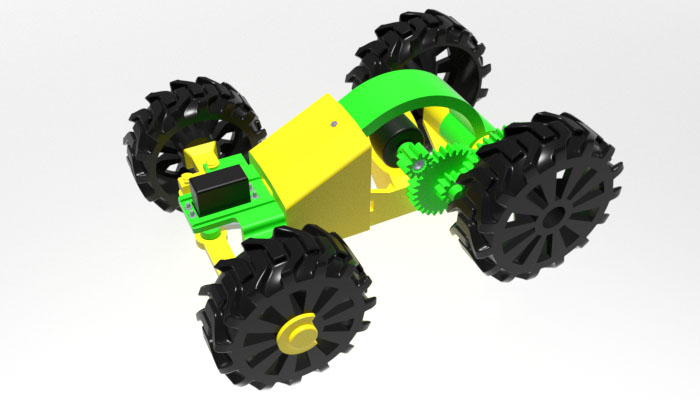
3D Model 17: 3D-Printable Remote Control Vehicle
Introduction

Introduction Video:
Download
Printed Parts List
Hardware
-
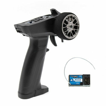
Remote Control and Receiver. Usually sold together as a combo. We are using a 4-channel receiver, although only two channels are used (for throttle and steering.)
-
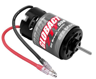
GLOBACT 550 electric motor, approx. 38mm in diameter. If you are going to use a different motor, do make sure its diameter is the same or it won't fit into the
motor holder on top of the platform.
-
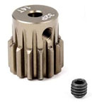
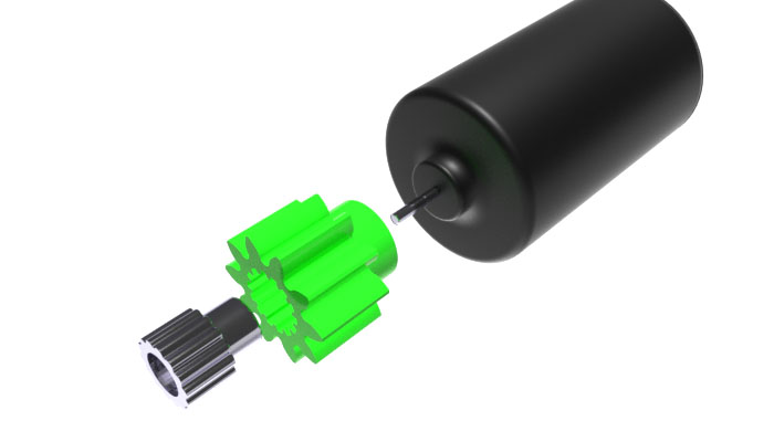
14T/32P Pinion with a 3.175mm shaft. This pinion serves as a connector between the motor and the 3D printed 10-tooth gear [rc11].
-
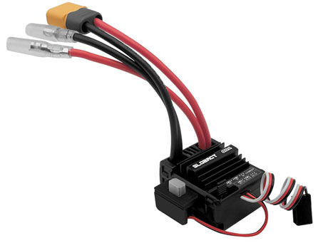
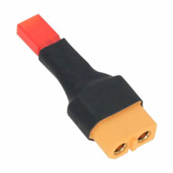
80A Brushed Motor Electronic Speed Control (ESC), XT60 connector.
Another connector can be used too as long as it is compatible with the battery's connector, or an appropriate adapter is used.
The servo plug (shown on the bottom right side of the photo below) is to be plugged into the receiver.
-
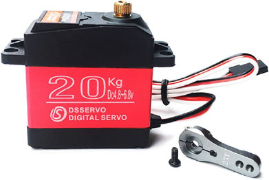
DS3218 Servo with an aluminum horn. The servo is to be plugged into the receiver.
-
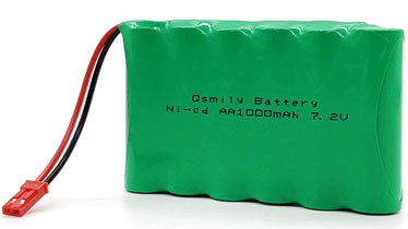
7.2v Battery, 1000mAh with a JST connector. This battery was used to test the vehicle, but a higher-capacity battery is recommended (at least 2000mAh).
The battery connector must match that of the ESC, or an adapter is needed.
-
Battery-to-ESC Adapter. Optional, only needed if the battery's output connector and ESC's input connector do not match.
-
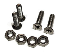
18 metric M3-12 countersunk bolts and 10 metric M3 nuts.
Assembly Instructions
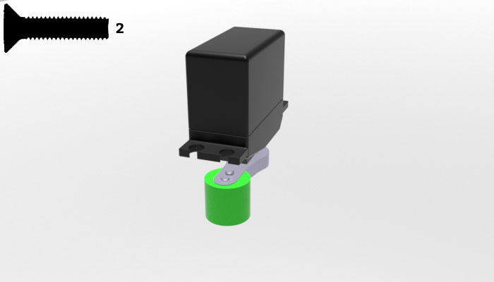
Step 2: Insert the 14T pinion into gear 10 [rc10], align holes. Mount the pinion onto the motor's shaft and secure with the tightening screw.
Step 3: Attach cam [rc08] to the servo's horn, secure with two bolts. Mount the horn onto the servo, secure with the two tightening screws.
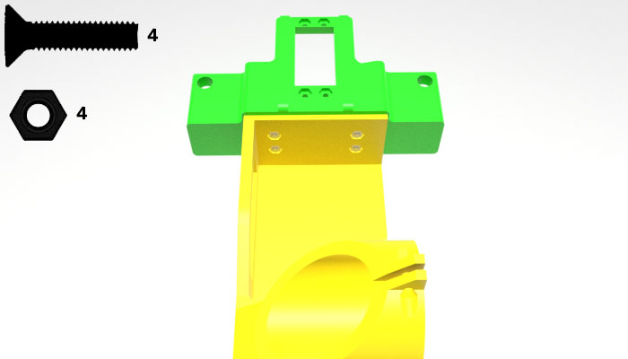
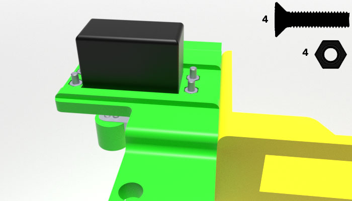
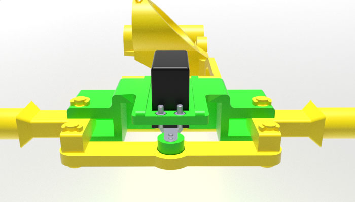
Step 4: Insert the servo into the front's rectangular hole, wires pointing towards the back, secure with 4 bolts and nuts.
Step 5: Insert two front shafts [rc13] into the front, align holes, secure with two long pins [rc15] and two small bushings [rc18]. Attach yoke [rc07] with the help of two short pins [rc16] and two small bushings [rc18], as shown below.
Step 6: Attach left front wheel [rc01] and right front wheel [rc02] to the left and right shafts, and secure with two bushings [rc17].
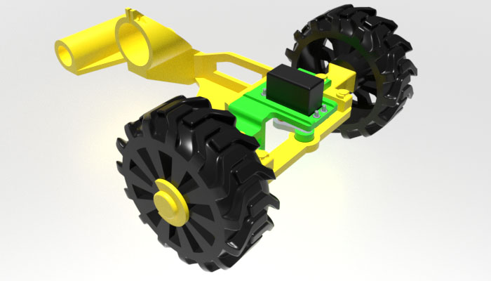
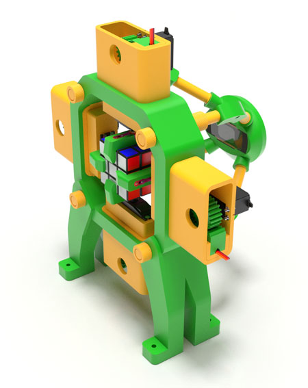
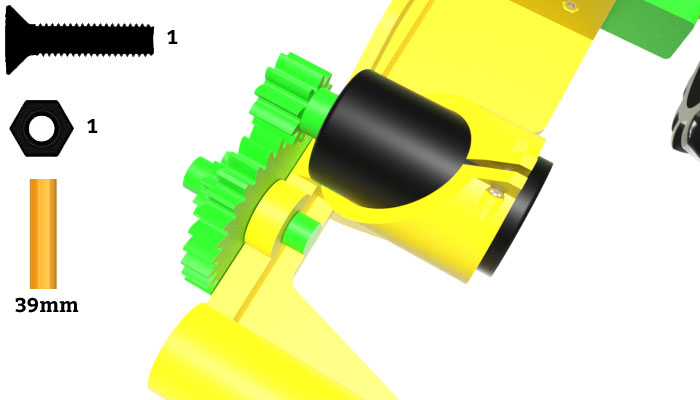
Step 7: Using a small saw or serrated knife, cut 39mm off a regular pencil, insert the pencil piece into the hexagonal hole in the platform, mount gear 10/30 [rc11] onto the piece and secure from both sides with caps [rc14]. Insert the motor into the motor holder at the top of the platform and mesh the two gears together. Secure the motor with a bolt and nut at the top of the motor holder.
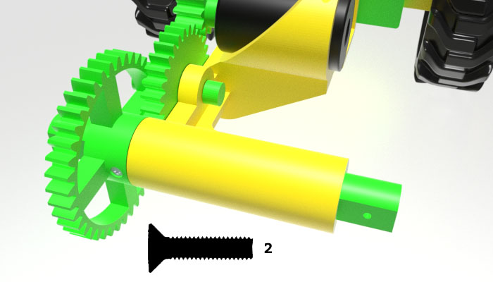
Step 8: Insert back shaft [rc09] into the shaft holder at the back of the platform, mount gear 40 [rc12] onto the back shaft, align holes, secure with two bolts on both sides of the gear.
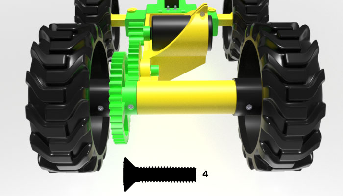
Step 9: Mount left back wheel [rc03] and right back wheel [rc04] onto the back shaft. Align holes, secure each wheel with two bolts on both sides of the wheel.
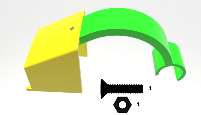
Step 10: Attach body front to body back with a bolt and nut.
Step 11: Attach the body to the front and platform by inserting the body front's tabs underneath the front and snapping the body back's over the platform's back shaft holder.