What's New
Our ChristMATH Ornaments a Winner on Thingiverse2023-12-24
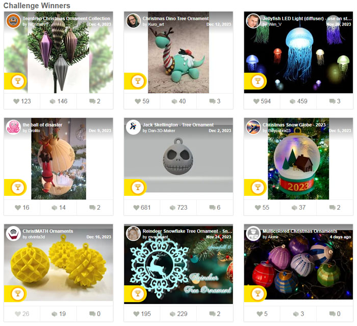
We submitted our ChristMATH ornaments to the Thingiverse-sponsored 2023 Tree Ornament Challenge and won a third place! Out of nearly 1,000 entries, we take pride in being selected as one of only 9 winners.
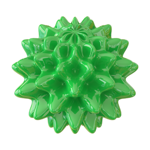
3D Model: 3D-Printed ChristMATH Ornaments2023-12-15
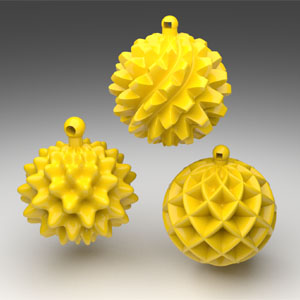
These Christmas tree ornaments are products of math and creativity. Each one is defined by a system of parametric equations and turned into a tangible and printable 3D object using an online calculator we have developed.
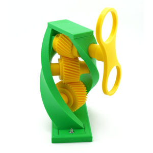
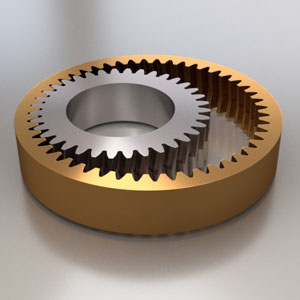
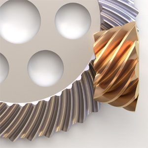
3D Model: Fully 3D-Printed Planetary Bevel Reducer2023-08-28
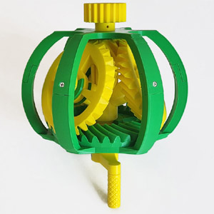
This wonderful mechanism is similar in principle to the planetary reducer, but instead of the regular spur gears it employs bevel ones, and the gears in the middle are tilted. When projecting the pitch cones of these bevel gears on a vertical plane, their triangular outlines combine to create an isosceles trapezoid that is completely filled.
The gear ratio for this particular model is 4:1. The model's diameter in its widest part is 20 cm (7 7/8").
Tutorial: How to Design Complex 3D Surfaces based on Transformation Matrices2023-04-12
3D surfaces can be defined parametrically, with three functions x(u, v), y(u, v) and z(u, v). While the parametric equations of simple surfaces such as a cylinder or sphere can be easily derived with just a pencil and paper, others, such as a spinning hypocycloid orbiting around a center which itself is rotating, seem impossibly complex.
This tutorial provides a system and method for deriving the equations of even the most complex of 3D surfaces using the multiplication of transformation matrices based on an online calculator we have developed.
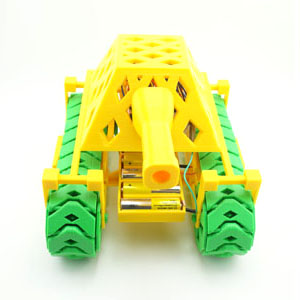
3D Model: RC Vehicle2022-09-21
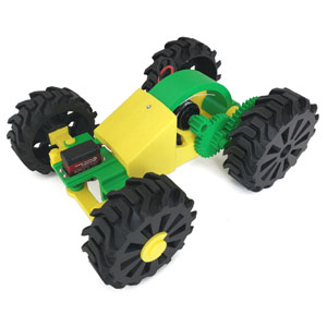
Who can resist the pleasure of driving a radio-control car? And now you can raise the enjoyment a few notches by building your own car completely from scratch, and learn along the way what an RC toy is like under the hood, both the electronics and mechanics of it.
This RC vehicle is fully 3D-printed, with the exception of motors, electronics, a pencil and a few bolts and nuts. The electronic parts are readily available and relatively inexpensive. Absolutely no soldering is required to put it all together. The vehicle is designed with an "open" architecture in mind -- the power train and steering mechanism are intentionally exposed for all to see.
Tutorial: How to Model a Tricky Part Based on a Drawing2020-10-25
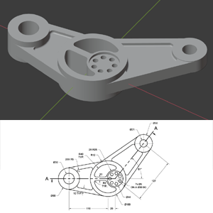
This tutorial explains how to model a tricky part based on a technical drawing in Blender 2.9. The drawing, which we downloaded from GrabCad.com, poses a number of challenges. Specifically, it contains multiple joints between straight and cylindrical surfaces, as well as cylindrical and other cylindrical surfaces.
The tutorial begins with the solving of two geometry problems necessary to model this part, and then proceeds with the actual modeling, which is not a quick undertaking. We had to time-lapse some portions of the modeling process to prevent the video from being overly long.
Tutorial: How to Model Non-Circular Gears in Blender2020-01-14

This tutorial briefly explains the math behind non-circular gears, and demonstrates how to quickly design and test a pair of meshing non-circular gears in Blender 2.81 (earlier versions of Blender can be used too.)
The math is not exactly trivial, but we have developed an online calculator which completely shields you from all the intricacies of non-circular formulas. You do need to come up with an equation in polar coordinates for the first gear's pitch curve, and the calculator will generate the toothed outlines for both gears automatically. With the help of this calculator, you can design your own pair of unique, amazing and fully functional non-circular gears in minutes!
Tutorial: How to Model a 3D-Printable Part Based on a Tech Drawing in Blender 2.812019-12-23
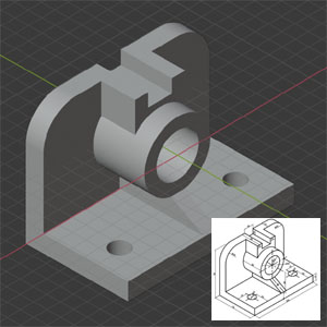
In this tutorial, you will learn how to model a 3D-printable part based on a technical drawing. Specifically, it focuses on how to couple cylindrical and flat surfaces, and also drill round through holes, without the use of the Boolean modifier.
The tutorial also demonstrates how to test a model for flaws from a 3D-printing point of view.
Tutorial: How to Animate a Split-Flap Display in 2.812019-12-15
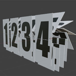
In this tutorial, you will learn how to model and animate a cool-looking old-fashioned split-flap display in Blender. A split-flap display is a great way to spice up any video requiring an eye-catching timeline indicator.
In a split-flap display, there are flaps attached via hinges to a rotating shaft. Each flap contains the picture of the top or bottom half of a digit or word on each side. Two adjacent vertically oriented flaps at the front of the display form a full digit or word. In Blender, the movement of the flaps can be animated using drivers. The driver formulas are not exactly trivial, but thanks to the online calculator we developed, all you need to do is copy and paste them from the calculator to Blender.
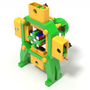
3D Model: Rubik's Cube Robot Carrying Case2019-11-05
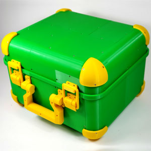
Wherever our Fully 3D-Printed Rubik’s Cube Solving Robot is shown off, it always generates lots of excitement and curiosity, be it a classroom full of kids, an office full of co-workers, or a trade show floor full of attendees.
Now there is a way to bring about even more excitement and curiosity, even before the robot is unveiled. Just carry it into the room in a briefcase that is also fully 3D-printed!
This carrying case was designed specifically with the robot’s dimensions in mind. The robot will fit in it perfectly with plenty of room for accessories. By no means a small project, the case requires a printer with a large print platform, such as Creality CR-10, as some of its parts are outright massive. There are 44 parts overall, and you will need a big bag of bolts and nuts to hold them together.
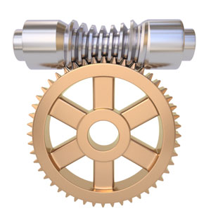
Tutorial: How to Instantly Design Throated Worm Drive in Blender 2.82019-10-29
This Blender 2.8 tutorial takes advantage of our newest Instant Throated Worm Calculator which takes the worm drive dimensions as the input, and calculates a worm-generating Python script as the output.
Unlike our original throated worm calculator, this one requires a single copy-and-paste operation per worm and very little post-processing.
Tutorial: How to Design a Gear Train in Blender 2.82019-04-20
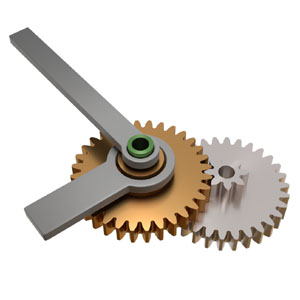
This Blender 2.8 tutorial explains how to design a simple 2-stage gear train with coaxial input and output shafts and given gear ratio (1:12 in this example.) The resultant mechanism can be used as a toy clock with the minute hand attached to the input shaft and hour hand to the output shaft.
The tutorial uses a short Python script to compute the number of teeth for each of the gears involved. It also demonstrates how to turn a gear with a low number of teeth and profile shift to a solid object without creating overlapping faces.
Tutorial: The Math Behind Hyperboloidal Gears and How to Model them in Blender2019-03-22
Hyperboloidal gears are essentially regular spur gears with their top and bottom twisted in the opposite directions. A hyperboloidal gear's reference surface is a hyperboloid, which is a surface obtained from a regular cylinder by twisting its top and bottom.
Two identical hyperboloidal gears are capable of transmitting rotation at any angle between 0° and 90° with the gear ratio of 1. This tutorial explains the math behind turning two touching cylinders into mating hyperboloids given the cylinders' dimensions and desired shaft angle, and how to model and test a pair of meshing hyperboloidal gears in Blender.
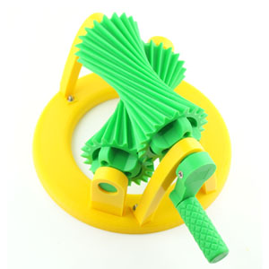
3D Model: Mechanical Spinning Top2019-03-22
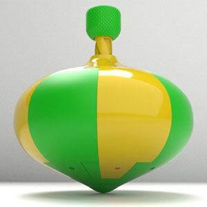
This fully 3D-printed mechanical spinning top is not only a fun toy, but quite educational too, and in more ways than one. Just like any spinning top, it demonstrates a fascinating physics phenomenon known as the gyroscopic effect, which prevents the toy from falling over while spinning. Also, nestled inside is a neat little mechanism which converts the reciprocal motion of the spiral rod to the one-way rotational motion of the spinning top's body. It is called the overrunning clutch, and we have managed to make it fully 3D-printed, even the torsion springs!
This fairly massive toy measures 20cm in its widest section, and not exactly a small project. However, the parts are designed in such a way that they are very easy to print and, with one exception, require almost no support.
3D Model: Servo-Driven Digital Clock2018-12-02
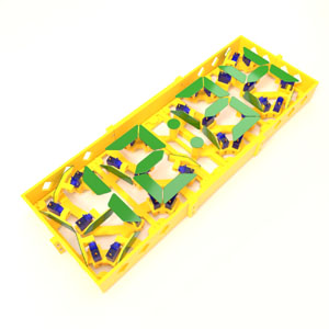
This fully 3D-printed clock is probably unlike any other digital clock you have seen. While in a regular LCD or LED-based digital clock the 7 segments for each of the four digits are switched on and off, the segments of this clock physically pivot in and out of view with the help of 28 individually controlled servo motors. The servos are connected to an array of servo controllers operated by a Raspberry PI application.
This huge clock (23" x 8") is sure to be an attention grabber and a great conversation piece in a crowd of computer and robotics nerds. And it shows precise time too!
Tutorial: How to Design a Threaded Surface in Blender2018-10-02
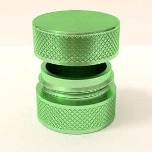
In this tutorial, you will learn how to model 3D-printable objects equipped with threaded surfaces, such as containers with screw-on caps, bolts, nuts, etc. Specifically, the tutorial focuses on designing a round jar with a screw-on cap that can be used to store small electronic components or fixtures. To make things more interesting, the jar and cap feature knurled surfaces.
The tutorial is based on a calculator which spits out a Python script that generates a threaded surface with a flattening thread profile.
3D Model: Hyperboloidal Gear Model2018-10-02
This gear model is full to the brim with mathematics, and it works well, too. The reference surface of each of these two gears is the one-sheet hyperboloid, which is formally defined as a "surface of revolution obtained by rotating a hyperbola about the perpendicular bisector to the line between the foci." Also, the bearings for the top gear are shaped as parabolas, and the base is a plain circle.
This model transmits rotation between shafts crossed at 45°.
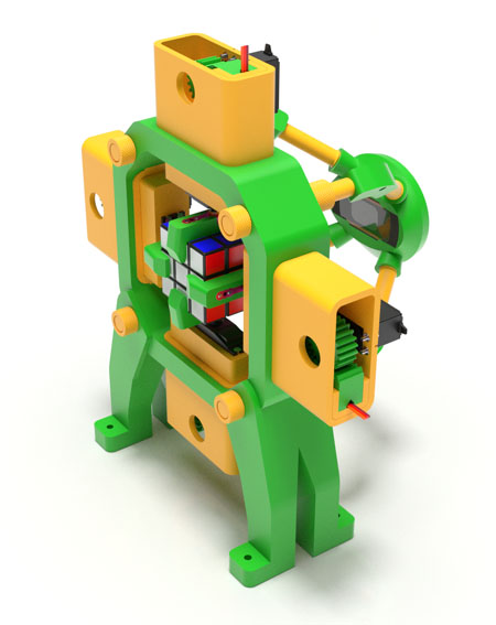
3D Model: Fully 3D-Printed Rubik's Cube Robot2017-08-15
This Rubik's Cube solving robot is fully 3D-printed. Other than the servos, servo horns, electronics and a few dozen bolts and nuts, it does not have a single traditionally manufactured part. If you have a 3D printer, less than $200 to spare, and some patience, this smart and beautiful machine can be adorning your own desk for everyone's enjoyment.
This robot has everything any serious robot does -- arms, servos, gears, vision, artificial intelligence and a task to complete. If you want to introduce robotics to your kids or your students, this is the perfect machine for it.
Our RC Tank Featured on Thingiverse2017-07-17
We are happy and proud to announce that our RC tank is now featured on Thingiverse!
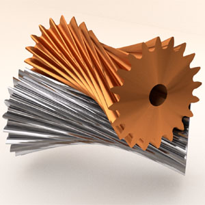
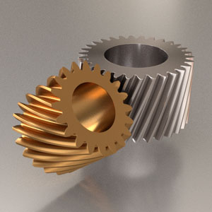
3D Model: 3D-Printable Screw Gear Model2017-05-25
Our collection of 3D-printable gear mechanisms would be incomplete without the model of a screw gear drive. Screw gears are regular helical gears mounted on non-parallel, non-intersecting shafts. They are also known as crossed helical gears.
The shape of this screw gear drive was inspired by the DNA molecule. In this particular model, there are three gears mounted at 45° to each other, but the shaft angle can be any number between 0 and 90°. Our screw gear calculator allows you to model the outlines of two meshing screw gears in Blender instantly.
3D Model: 3D-Printable Tank with Single-Piece Tracks2017-05-14
This tank does not require a single bolt or nut. You just print the parts, snap them together, connect the motors and electronics, and it is ready for battle. It shows excellent off-road capabilities, and turns on a dime. Each of this tank's two tracks is printed in a single piece, thus eliminating the need for assembly hardware.
The machine shown here is powered with a Picaxe 20M2 microcontroller installed on a 300-hole mini-breadboard. There is also an H-bridge motor driver, an IR sensor, a couple of resistors and capacitors, and a whole bunch of jump cables. The entire set of electronic components used here can be bought on eBay for just a few dollars. The tank is operated with a regular Sony TV remote control.
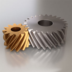
Tutorial: How to Design Screw Gears in Blender2017-05-12
In this tutorial, you will learn how to quickly model a pair of meshing gears mounted on non-intersecting, non-parallel shafts. These gears are known as screw gears, or crossed-helical gears. Screw gears are typically mounted at 90° to each other, but it does not have to be that way. Any angle between 0 and 90° can be used. On this picture, a 50° shaft angle is used.
The tutorial will also demonstrate how to test a pair of screw gears for compatibility using Blender's rigid body physics engine.
Tutorial: How to Instantly Design Internal/External Gears in Blender2017-05-07
In this tutorial, you will learn how to instantly model the outlines of an internal/external gear pair in Blender using an online calculator we have developed, and then turn these outlines into full-bodied gears and test them for compatibility using Blender's Rigid Body Physics engine.
The tutorial will also demonstrate how to add a sun (center) gear to the system to produce a fully functional planetary mechanism, and how to test it with the rigid body physics engine too.
Tutorial: How to Instantly Design Straight, Helical and Herringbone Gears in Blender2017-05-02
In this tutorial, you will learn how to model involute gears instantly using our brand-new online calculator. With the help of this instant gear calculator, a pair of perfectly meshing straight, helical or herringbone gears with involute teeth and profile shifts can be created in under 90 seconds, as demonstrated in the tutorial.
Helical gears are stronger than straight gears due to a greater load bearing surface area, but due to the curved shape of their teeth, they are subject to an axial load. This problem can be solved with the help of herringbone gears. A herringbone gear is essentially two helical gears with opposite hands, stacked on top of each other.
Tutorial: How to Design a Rack-and-Pinion in Blender2017-03-22
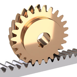
A Rack-and-Pinion refers to a gear mechanism which converts rotational motion into linear motion. It consists of an involute gear wheel (pinion) and a mating toothed bar (rack). The teeth of a rack-and-pinion pair can be straight or helical. A rack-and-pinion is found in the steering mechanism of vehicles and many other places.
In this tutorial, you will learn how to design a rack-and-pinion mechanism in Blender and test it with Blender's rigid body physics engine. Both straight-toothed and helical gears are covered.
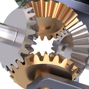
3D Model: 3D-Printable Automotive Differential2017-02-16

Every automobile's got one, and this motorized model gives you a sneak peek of what's inside that large round housing where the drive shaft and the two wheel shafts meet.
The automotive differential transmits power from the engine to the driving wheels while allowing them to rotate at different speeds. There are four bevel gears in the center of a differential, and the pinion and ring gears (shown here in yellow) are usually of the bevel kind too, but this particular model uses a hypoid gear pair instead. The model is powered by a 6V electric motor equipped with a speed reducer.
3D Model: 3D-Printable Automotive Differential2017-01-30
When a car turns, its driven wheels operate at different speeds as the inner wheel has to travel a shorter distance to complete the turn. This is made possible with the help of the automotive differential, an ingenious mechanism which splits the engine's torque between the two wheel shafts and enables one of the wheels to revolve faster than the other when the driving conditions call for it, such as during a turn.
The automotive differential transmits power from the engine to the driving wheels while allowing them to rotate at different speeds. There are four bevel gears in the center of a differential, and the pinion and ring gears (shown here in yellow) are usually of the bevel kind too, but this particular model uses a hypoid gear pair instead. The model is powered by a 6V electric motor equipped with a speed reducer.
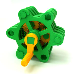
3D Model: 3D-Printable Walking Gear Bot2017-01-14
This mechanism, through the clever use of planetary gearing, converts simple rotation to a walking motion. The Walking Gear Bot is driven by a single electric motor powered by four AA batteries. This robot is built around 11 meshing involute gears, and there are 36 printable parts overall.
The Walking Gear Bot is an all-around fun and educational mechanical toy enjoyable by adults and kids alike.
3D Model: 3D-Printable Eccentrically Cycloidal (EC) Model2016-12-16
Most gearing mechanisms known today were invented decades or even centuries ago. Not so with the Eccentrically Cycloidal (EC) drive: it is so new the ink is still not dry on its patents! This 3D-printable model is made available to the public with the explicit permission of the patent holder. Print your own EC model and become one of a very few human beings to ever lay hands on this new and remarkable invention.
This futuristically looking mechanism is very efficient and extremely compact. The gear ratio in this particular EC drive model is 1:9, an almost impossible feat for a standard involute gear pair.
Tutorial: How to Design an Eccentrically Cycloidal (EC) Drive2016-12-16
The recently invented Eccentrically Cycloidal (EC) drive is closely related to the hypocycloid drive described in our Tutorial #5. From the modeling point of view, these two mechanisms are very similar as they are built around the same basic shape - the cycloid disk. In fact, both tutorials use the same online calculator. With the help of this calculator, designing a functional EC drive will only take a few minutes. This tutorial also tests the EC gear pair for compatibility using Blender's Rigid Body Physics engine.
Be aware that the EC drive is covered by a number of US and international patents. This tutorial was created with the explicit permission of the patent holder.
3D Model: 3D-Printable Hypoid Gear Drive Model2016-11-11
Hypoid gears are similar to bevel gears but the pinion and wheel in a hypoid pair have non-intersecting axes. Unlike our bevel gear model, where the gears are overhang-mounted, the pinion in this model is straddle-mounted (i.e sandwiched between two bearings) for a much sturdier assembly. Click here to see the video of this model in action, and download the .stl files.
Tutorial: How to Design a Hypoid Gear Drive in Blender2016-11-11
A hypoid gear drive is similar to a bevel gear drive, but the axes of the pinion and wheel in a hypoid drive do not intersect. Hypoid gears are widely used in automotive and other industries. They offer high gear ratios, good efficiency and sturdiness of the assembly.
The math behind hypoid gears is daunting, but thanks to the online hypoid gear calculator we have developed, you don't need to worry about it at all. This concise tutorial shows you how to design your own hypoid gear pair in Blender easily.
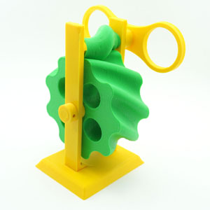
3D Model: 3D-Printable Hypocycloid Speed Reducer2016-10-13
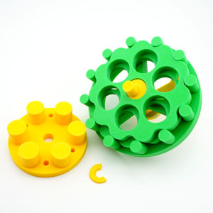
The hypocycloid speed reducer is truly an amazing invention. We have designed a 3D-printable model of the hypocycloid drive in such a way that you can actually see the inner workings of this remarkable mechanism. Click here to see the video of this model in action, and download the .stl files.
3D Model: 3D-Printable Hypocycloid Speed Reducer2016-10-12
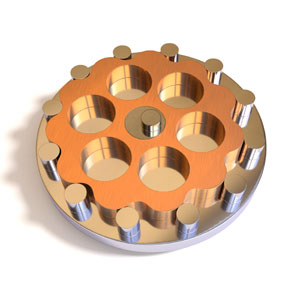
In a hypocycloid (or simply cycloid) speed reducer, a flower-shaped gear called cycloid disk moves around a stationary ring of round pins in a cycloidal motion, driven by an eccentric bearing or cam connected to the input shaft. Radial holes on the face of the cycloid disk in turn drive the pins of the output shaft. Hypocycloid drives are widely used in the industry due to their excellent characteristics, such as wide range of gear ratios, compact size, smooth transmission, high efficiency, high overload capacity, low noise, long service life, and compact design.
With the help of our tutorial, you can design your own hypocycloid drive in Blender in a matter of minutes.
3D Model: 3D-Printable "Perpetual" Flip Calendar2016-09-22
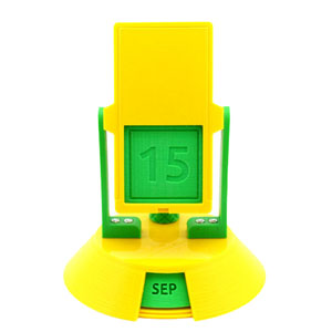
Inspired by vintage flip calendars of the 60s, this 3D-printed "perpetual" desktop calendar needs no batteries. You flip it every day to advance the date and gravity does the rest. Click here to see the video of this calendar in action, and download the .stl files.
Tutorial: How to Design a Planetary Gear Mechanism in Blender2016-08-16
The Planetary, or Epicyclic, gear mechanism consists of one or more planet gears revolving around a central, or sun gear. Typically, the planet gears are mounted on a carrier which itself rotates relative to the sun gear. A planetary system also incorporates an outer ring gear which meshes with the planet gears. The teeth of the ring gear point inwards. Gears like that are often referred to as internal. The planet and sun gears are regular, or external, gears, and the design process for those was covered in our Tutorial #1. However, the design of an internal/external gear pair requires its own set of formulas and its own calculator. This tutorial covers the modeling of a profile-shifted ring/planet gear pair, and sun gear.
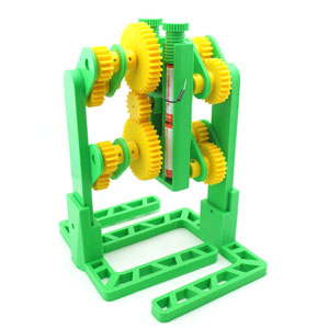
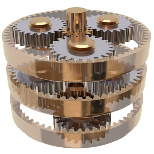
3D Model: 3D-Printable Planetary Gear Model2016-08-16
This stackable model allows for an unlimited number of stages. Even with 3 stages shown here, this planetary gear reducer packs an impressive 1:216 gear ratio. Designing planetary gears in Blender 3D is described in detail in our Tutorial #04.
Tutorial: How to Design a Bevel Gear Drive in Blender2016-07-06

Bevel gears, also sometimes called conical gears, are gears where the axes of the two shafts intersect and the tooth-bearing faces of the gears themselves are conically shaped. Bevel gears are usually mounted on shafts intersecting at 90°, but can be designed to work at other angles as well. In fact, in this tutorial we are designing a bevel gear pair with the shaft angle of 100°. Also, the gear wheels designed in this tutorial feature curved teeth and an involute tooth profile. At the end of the tutorial, the gears' compatibility is successfully tested with Blender's Rigid Body Physics engine.
3D Model: 3D-Printable Model of Bevel Gear Drive2016-07-06
Add this functional bevel gear drive model to your collection of 3D-printable mechanisms! The model features bevel gears with involute tooth profiles, curved teeth and a non-right angle between the shafts. Designing bevel gears in Blender 3D is described in detail in our Tutorial #03.
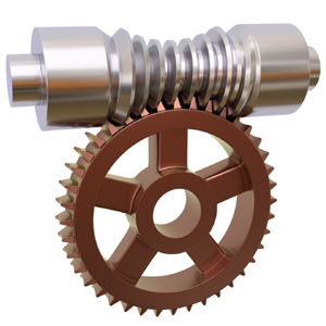
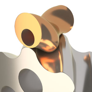
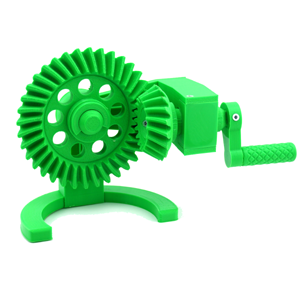
Tutorial: How to Design Globoid Worm Drive in Blender2016-06-10
Worm drives are ubiquitous! They can be found literally everywhere, from heavy machinery to acoustic guitars. Designing a simple cylindrical worm drive is not hard: just apply the Screw modifier to a trapezoidal tooth profile and you get the worm, then throw in a standard involute gear wheel with slanted teeth and you are done. The globoid (also known as throated) worm drive is far more involved. Its backbone is not a cylinder but an hourglass-like shape cut out of a torus. The globoid worm shaft is as beautiful as it is picky: finding a mating gear for it is not a trivial task. In this tutorial, you will learn how to create both a worm shaft and mating gear wheel in Blender, and test their compatibility using Blender's Rigid Body Physics engine.
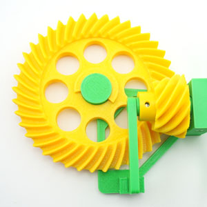
3D Model: 3D-Printable Model of Globoid Worm Drive2016-05-25
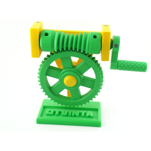
Nothing validates a mechanical design better than a functioning, physical model! The globoid gear drive, the subject of Tutorial #02, is now available as a collection of 3D-printable parts in STL format that assemble into a perfectly operational and aesthetically appealing hand-cranked desktop mechanism. The model makes a great conversation piece, and a fun and educational toy for your kids!
Tutorial: How to Model Geometrically Correct (Involute) Gears in Blender2016-03-20

Cogwheels are often depicted with straight and boxy teeth. However if you take a close look at a real-world gear wheel, you will notice that the sides of its teeth are not straight at all, and for a good reason. Two mating gears must stay in tight contact at all times, and most importantly, the direction of pressure one gear exerts on the other must remain constant to prevent vibration and noise. Leonhard Euler, a great mathematician of the 18th century, designed a gear profile satisfying these requirements with the help of the involute, a mathematical curve that can be described with a pair of simple parametric equations. In this tutorial, you will learn how to design a pair of perfectly meshing involute gear wheels in Blender in just a few minutes.